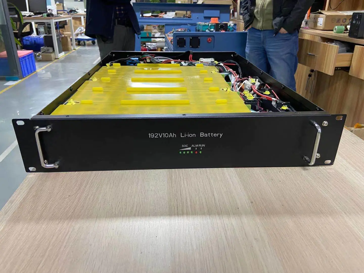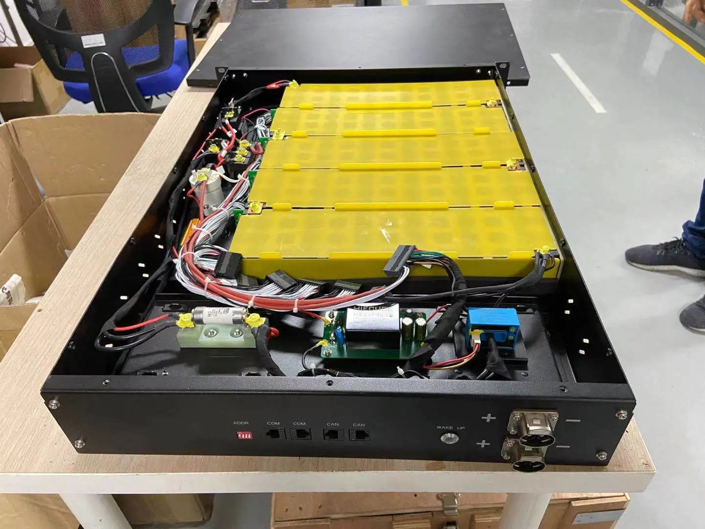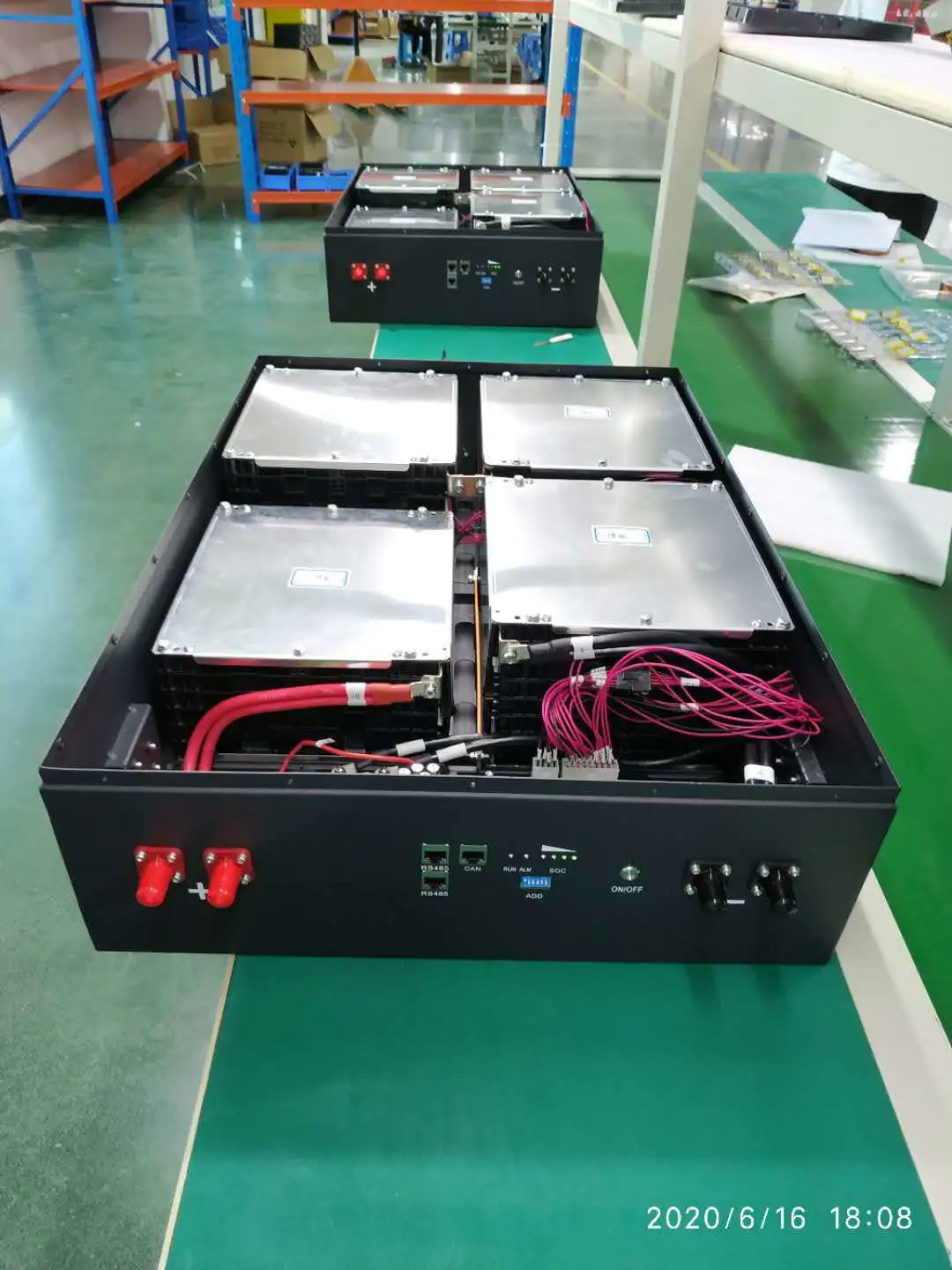
Analysis of Vehicle Lithium Ion Power Battery System and Charging Technology of Charger
EV battery
The comparison of lithium battery charging methods
by:Vglory
2020-12-04
Source: 2020 -
04 -
At 19:00 11 hits: based on UC3842B and STM8S103F2 lithium battery charger is introduced with the development of portable devices and power tools, battery performance requirements are also increasing, especially in rechargeable lithium batteries.
At the same time, the lithium battery charging circuit design and optimization are also constantly improve.
In this paper, design of lithium battery charging circuit is a kind of based on the three series of 10.
8 v battery intelligent lithium battery charger.
The experiment used battery model for South Korea's samsung inr18650 -
13 q type battery.
Rating of the battery capacity is 1300 mah, the rated working voltage of 3.
60 v, when the battery voltage to 4.
20 v, the default state, charge a battery needs to use the cc -
cv(
Constant current -
Constant pressure)
Charging.
Single chip microcomputer and current mode controller based on STM8S103F2 UC3842B adjustment, through the hardware and software combination to realize constant current constant voltage charging process and transformation.
Introduces in detail the hardware and software principle of lithium battery charger, mainly introduced the realization of the constant current constant voltage charging, and the experimental results of the charger is analyzed.
Charging ways is lithium battery charging ways is not much at home and abroad, which can be roughly divided into the following two kinds: 2.
This method is simple dc charging mode.
By 220 v mains voltage transformer is converted into a voltage value, with a constant current charging directly to lithium batteries, until the battery voltage reaches a certain value.
This method is simple, fast charging time, but is a big damage for the battery, it is hard to the battery.
Use this charger to cause a decline in battery life for a long time.
Figure 1: conventional charging mode 2.
Two conventional charging ways as shown in figure 1, this is the most common method.
When insert the battery charger, the charger first enter a state of pretreatment, pretreatment condition mainly check the battery.
Using about C / 15 to mild rechargeable battery charging current, test voltage can reach 2.
5 v threshold.
Otherwise, as battery damage;
If you can, it will turn into constant current area, with high current (
About 1 c)
A quick recharge the battery pack.
When the constant current charging at 4.
2 v threshold voltage, the battery into the constant pressure area.
In the constant pressure, battery charge at constant pressure.
Along with the increasing battery voltage, charging current continues to decrease, until the charging current drop to 10 to C/C / 15, stop charging, the end of the charging status.
In charge efficiency and cell loss, direct current method is far lower than the traditional method.
Although the charging time is short, but use frequency is still very low.
Compared with the traditional method of charging effect and cell loss can meet the requirements, and easy to implement than other methods.
Therefore, the traditional method has already become the most commonly used lithium battery charging method.
The design of this system is based on the traditional methods.
Figure 2: UC3842B simplified diagram chip is introduced and the circuit structure of this system is mainly used in high-performance UC3842B current mode control chip.
3.
1 UC3842B introduce UC3842B chip is a kind of high performance current PWM controller.
The chip circuit switching frequency is adjustable, with current feedback and the characteristics of the voltage feedback loop control, high voltage regulation and load regulation.
Peripheral circuit is simple, convenient installation, good performance, low prices.
UC3842B chip internal mainly includes: 5 v reference voltage, input under-voltage lockout circuit, error amplifier, oscillator, pulse width modulator.
Figure 2 is 8 needles simplified block diagram of UC3842 chip encapsulation.
The function of each foot are as follows: 1 foot is the output of the error amplifier;
Foot 2 is the inverse input error amplifier, usually through the output resistor voltage divider is connected to the switch power supply, start the voltage feedback use;
Foot 3 for current sampling needle;
4 for input PWM Foot
Custom message
Related Products

![[Industry Solution] How does outdoor backup power supply cope with extreme climate? Practical analysis of lithium solar cells](https://img80003422.weyesimg.com/uploads/vglorylibattery.com/images/17502322689034.jpg?imageView2/2/w/1920/q/70/format/webp)