Balance car lithium ion battery how to maintain
EV battery
How to properly maintain the lithium battery pack?
by:Vglory
2021-04-01
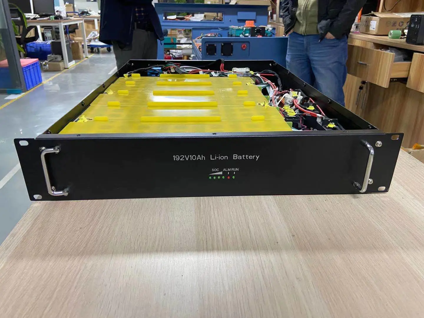
Analyze how to maintain lithium battery packs. Lithium batteries have been integrated into our daily lives. Commonly used products we can process are electric motorcycles, portable power tools, plug-in hybrid cars, etc. As long as the battery is in contact, the lithium battery will exist. The power field effect transistor is a key safety function in the battery handling system (BMS), and its important purpose is to isolate the battery pack from the load or charger under abnormal conditions. This article will discuss the detection block and its application in power field effect transistors to ensure the safe operation of lithium battery packs. The power FET function block does not look messy: connect the FET to the charger or load; when a fault occurs, turn off the FET. In order to work normally as an energy field effect transistor, planning engineers need to know the load conditions, battery pack constraints, and functional block circuits. In the battery processing system, the power field effect transistor is controlled by comparing battery voltage, battery pack current, temperature, load, and charging monitor. In a system, there are three ways of constructing function blocks: (1) Through discrete components, these components need a rated board space, and the program engineer must have a deep understanding of each sub-block. (2) The power field effect transistor integrates most of the sub-function blocks and can be used as a supporting IC for multi-core monitor/equalizer. Power Field Effect Transistor (FET) technology is useful in applications where the number of cores (16 batteries) is high, such as solar farms and smart grids. (3) The powerFET function block in the fully integrated BMSIC (such as ISL94202, ISL94203, ISL94208). The functions of these three methods are roughly the same. This article explains the inherent functions of each sub-block and the planning considerations for different applications. Consider the circuit configuration in Figure 1. The system is equipped with a high-side series field effect transistor connected to the engine. The on-off (open) state of the power field effect transistor depends on the battery voltage, charge and discharge current, temperature, and the state of the monitoring pin. Any failure described in the sub-block may cause the FET to turn off once or twice. Vcell detection Vcell detection without cell balance is used to monitor the battery status of overvoltage, undervoltage, and open circuit. The undervoltage state of the battery is very important for detecting the no-load state of the battery pack and preventing the battery from falling out of the effective area of u200bu200bthe voltage. The use area of u200bu200blithium batteries is 2.5v-4.2v. The use area of u200bu200blithium polymer battery is 2.5v-3.6v. According to the battery chemistry and plan, the battery's bound voltage determines the limit of the fully loaded and unloaded battery. When charging the battery, the upper voltage limit cannot be exceeded, otherwise the battery will be damaged. Most BMS integrated circuits continue to monitor overvoltage and undervoltage conditions regardless of battery charging. After measuring all the cells in the battery, Chen said that the total voltage difference between the strongest and weakest cells in the battery is useful. Large battery voltage difference can distinguish battery or open line operation. Most systems have an open circuit test to ensure that the measurement system is connected to the battery. The open circuit test is not as good as the battery voltage measurement, and the calculation result of the battery voltage difference can be used as an early warning of system failure. Open battery operation means that the open circuit inside the battery may be damaged by external connections. Work may happen slowly or suddenly. Possible reasons for open-circuit battery operation include aging, poor battery manufacturing, or long-term exposure to harsh conditions. Damage to the external connection is usually caused by the poor structure of the battery pack. When the battery pack is connected to the load, a large amount of input current may appear. The injection current multiplied by the impedance mismatch of the battery will cause a serious mismatch in the battery voltage. When Chen works, some chips will be delayed, and some will not. Current detection Most battery systems used to measure current have three current comparators: discharge short circuit (DSC), discharge overcurrent (DOC) and charge overcurrent (COC). Each comparator has a delay, allowing the current to exceed the limit for a period of time before being used. The load is less controlled than the charger, so fast current discharge detection is required to turn off the power FET to prevent damage to the battery or the power FET itself. When the DSC is working, the power field effect transistor is often turned off with a delay of tens to hundreds of milliseconds. DSC delay includes on-time delay and power field effect transistor off time. When the gate and the power supply are connected by the isolation resistor, the power field effect transistor is disconnected. The resistance and the gate capacitance form an RC circuit, and the RC circuit determines the cut-off time of the FET. Disclaimer: Some pictures and content of articles published on this site are from the Internet. If there is any infringement, please contact to delete.
Custom message
Related Products

![[Industry Solution] How does outdoor backup power supply cope with extreme climate? Practical analysis of lithium solar cells](https://img80003422.weyesimg.com/uploads/vglorylibattery.com/images/17502322689034.jpg?imageView2/2/w/1920/q/70/format/webp)