Analysis of Vehicle Lithium Ion Power Battery System and Charging Technology of Charger
EV battery
Design of a new type of lithium battery management system
by:Vglory
2021-04-08
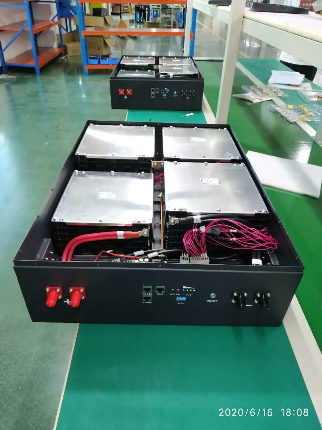
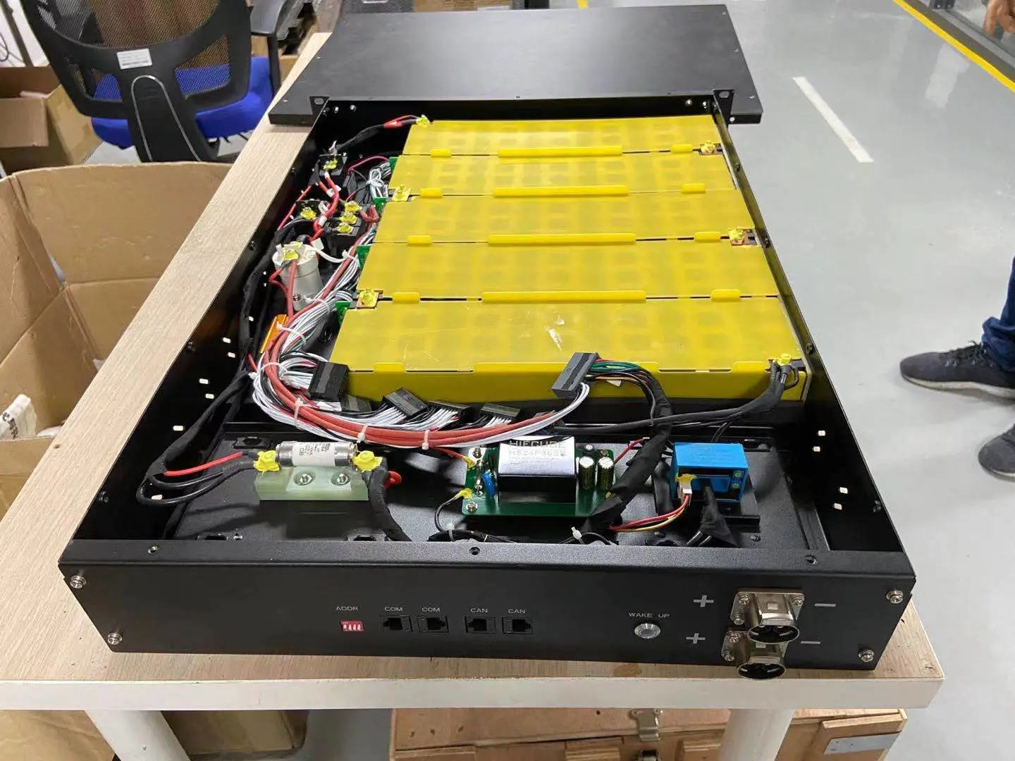
Designed and implemented a new lithium battery management system battery conduction system (management system, BMS), which includes technology and microcomputer detection, performs dynamic monitoring of battery cells and battery operation conditions, can accurately check the remaining battery capacity, battery charge and discharge Maintenance, the best operating conditions, the decline in working capital, and the service life. In this paper, some advanced technical achievements at home and abroad are integrated, and a new type of lithium battery management system is designed and implemented. The management structure adopts modular and distributed planning, and the system includes a secondary control structure, namely, a local measurement module and a central processing module. During this period, the important function of the central processing module is to communicate with the host computer through the RS232 interface, and to connect with the local measurement module through the CAN bus network method. The important functions of the local measurement module are data acquisition (importantly used for temperature, current and voltage data acquisition), charge and discharge control, power measurement, single cell balance, and the use of CAN bus technology to communicate with the central processing module. 1. System hardware planning The battery processing system planned in this article is mainly used in electric vehicles and some underwater equipment. Therefore, the system planning should have a reasonable structure, advanced technology, and strong scalability; the technical accuracy of the system parameters is high. Therefore, the planning of this battery management system should complete the following functions: 1) Collect battery information in real time, including the total battery pack voltage, single battery voltage, charge and discharge current, temperature and other parameters; 2) Remaining power measurement and display; 3) Available Supply data transmission interface to complete the communication with CAN bus and upper computer; 4) Good human-computer interaction, safe and reliable system, and strong anti-interference ability. 2. Hardware planning of the local measurement module 2.1 The voltage acquisition module's single battery terminal voltage is an important basis for calculating the remaining battery, the choice of charging and discharging methods, and the evaluation of the running state, so the premise of monitoring the battery pack is that there must be a reasonable single Method of measuring the terminal voltage of the body battery. However, due to the large number of batteries in the battery pack, the high total voltage, and high measurement accuracy requirements, it is difficult to achieve power measurement. The working principle of the voltage monitoring plan is as follows: In the first step, the single-chip microcomputer controls the multi-channel switches kn-1 and kn-2 (numbers between n1 and 7), synchronously connect the capacitors at both ends of the corresponding battery, start the capacitor charging, and achieve the purpose , The capacitor voltage is the same battery voltage; the second step is to disconnect the kn-1 and kn-2 multiplexers controlled by the MCU, close the K1 and K2 switches, and connect them to the A/D module of the MCU for measurement. When measuring time, the module chose the method of average value measurement based on the consideration of preventing the effect of the instability of the battery terminal voltage. This method can easily use the A/D unit inside the microprocessor without adding A/D module rating, improving planning efficiency and saving money. Usually in the actual circuit, a relay can be used to complete the analog switch. 2.2 Current acquisition module Regarding the measurement of dynamic current during charging and discharging, this article uses LEM's ltsr25-np current sensor. This element is a closed-loop multi-range current sensor, which is compensated according to the Hall effect and adopts the unipolar voltage method. It has the advantages of high measurement accuracy, no insertion loss, good linearity, and strong current overload capability. The measurement accuracy can reach ±0.2% below 25℃. The rated current is 25 amperes, and the maximum measurable current is 80 amperes. The current sensor can convert the charge and discharge current into a voltage signal of 0 to 5 volts, and then connect it to the A/D unit of the microcontroller to measure the charge and discharge current. Disclaimer: Some pictures and content of articles published on this site are from the Internet. If there is any infringement, please contact to delete. Previous: Solutions to common battery failures
Custom message
Related Products


![[Industry Solution] How does outdoor backup power supply cope with extreme climate? Practical analysis of lithium solar cells](https://img80003422.weyesimg.com/uploads/vglorylibattery.com/images/17502322689034.jpg?imageView2/2/w/1920/q/70/format/webp)