Can today's electric cars charge quickly , Will fast charging affect the battery
EV battery
How to correctly measure the power consumption of low-power communication modules?
by:Vglory
2021-03-30
Low power consumption is very important for the interconnection of all things. Basically, IoT nodes need to be powered by batteries. We need to correctly measure the power consumption of the wireless module, and accurately estimate how large batteries need to be used. Lithium battery manufacturers will explain the detailed measurement methods. In many applications of the Internet of Things, the available power is limited. The battery has a certain degree of self-discharge. In the worst case, the actual power used is only about 70% of the nominal power. For example, the CR2032 button battery has a nominal capacity of 200mAh, but only 140mAh can be used. This is an extremely normal phenomenon. Since the battery power is so limited, it is extremely important to use low-power solutions when designing products, and reducing product power consumption is extremely important! Let us first understand the commonly used methods of measuring power consumption, and understand these methods of measuring power consumption before we can optimize product power consumption. 1. Power consumption measurement The power consumption test of the wireless module mainly measures two kinds of tests: static current and dynamic current. When the module is in the dormant or standby state, since the current does not change and maintains a static value, we call it a quiescent current. At this time, we can use a traditional multimeter to measure, just connect a multimeter in series with the power pin to get the value that needs to be measured, as shown in Figure 1. Figure 1 When the multimeter tests the emission current when the module is working normally, the entire current is in a state of change, which we call dynamic current. The response time of the multimeter is relatively slow and it is difficult to capture the changing current, so the multimeter cannot be used for measurement. At this time, we need to use the oscilloscope and current probe to measure. The measurement results are shown in Figure 2. Figure 2 Current probe measurement results Figure 2. Battery life calculation The communication module often has two working modes, working mode and sleep mode, as shown in Figure 3 below. Figure 3 The average current is as shown in the above figure, the sending interval between two sending packets is 1000ms, and the average current is calculated: that is, the average current in 1 second is about 2.4mA. If you use a CR2032 to supply power, ideally It can be used for about 83 hours, about 3.5 days. What if we extend the sending interval to 1 hour? Similarly, it can be calculated by the above formula that the average current in 1 hour is only 1.67uA. The same CR2032 battery can support the device to work for 119,760 hours, about 13 years! It can be seen from the comparison of the above two examples that increasing the time interval between sending packets and prolonging the sleep time can reduce the power consumption of the whole machine and enable the device to work longer. This is why products in the wireless meter reading industry generally have a long service life, because they only send data once a day. 3. Common power consumption problems and reasons To keep the product low power consumption, in addition to increasing the transmission interval, there is also to reduce the current consumption of the product itself, which is the Iwork and ISleep mentioned above. Under normal circumstances, these two values u200bu200bare consistent with the chip data manual, but if the operation is improper, problems may occur. When we tested the emission current of the module, we found that whether the antenna is installed has a great influence on the test result. When measuring with an antenna, the current of a product is 120mA, but if the antenna is unscrewed, the test current soars to nearly 150mA. The abnormal power consumption in this case is mainly caused by the mismatch of the RF terminal of the module, which causes the internal PA to work abnormally. Therefore, the actual test must be loaded with the test. We found that when the sending interval becomes longer and longer, the duty cycle of the operating current becomes smaller and smaller. At this time, the biggest factor affecting the power consumption of the whole machine is ISleep. The smaller the ISleep, the longer the product life. But it is possible that the test sleep current is too large, why is that? This may be caused by the configuration of the MCU. The power consumption of a single IO port of a general MCU can reach the mA level. In other words, if you accidentally miss or mismatch the status of an IO port, it may destroy the early low-power design. Let's take a product as an example to conduct a small experiment to see how big the impact of this problem is. Figure 4 Test result of low-power IO configuration of product A Figure 5 Test result of improper IO configuration of product A In the test process of Figure 4 and Figure 5, the same product is also configured in module sleep mode, and the test can be clearly seen The result is different. In Figure 4, all IOs are configured as input pull-down or pull-up, and the tested current is only 4.9uA. In Figure 5, only two of the IOs are configured as floating inputs, and the test result is 86.1uA. If the operating current and duration of Figure 3 are kept unchanged, the sending interval is 1 hour, and different sleep current calculations are brought in. According to the result of Figure 4, the average current of one hour is 5.57uA, and according to Figure 5, it is 86.77uA, a difference of about 16 times. It also uses a 200mAh CR2032 battery to supply power. The product can work normally for about 4 years according to the configuration in Figure 4, and the result is only about 3 months according to the configuration in Figure 5! In conclusion, extending the standby time of the wireless module should follow the following design principles: 1. Extend the packet sending interval as much as possible and reduce the current in the cycle; 2. Configure the IO status of the MCU correctly. Disclaimer: The articles published on this site are all from the Internet and do not represent the views of this site. If there is any infringement, please contact to delete WeChat: Disclaimer: Some pictures and content of the articles published on this site are from the Internet. If there is any infringement, please contact delete A: Should I choose a lithium battery or a lead-acid battery when using a UPS solution in a data center?
Custom message
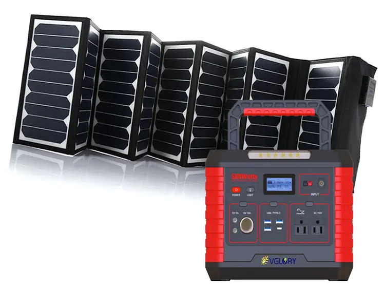
Related Products


![[Industry Solution] How does outdoor backup power supply cope with extreme climate? Practical analysis of lithium solar cells](https://img80003422.weyesimg.com/uploads/vglorylibattery.com/images/17502322689034.jpg?imageView2/2/w/1920/q/70/format/webp)